I thought it probably was due to the number of times it has fallen on the floor... :-)
So I decided to take a look inside.
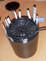
In theory, you should be able to dismantle it by simply turning the subwoofer base in the right direction... but during the assembly process of our subwoofer someone spilled too much glue...
So I forced my way in with some pieces of plastics cut from an old badge...
Well... many pieces of plastics...
And a screwdriver to finish the job...
Anda Ta-Daaaaa, here is the mini-subwoofer!
To dismantle it, I fundamentally broke it's 4 clips
And here is the spilled glue that forbid me to open the subwoofer by simply turning it's base
The subwoofer it it's resonant box
But I noticed that, interestingly, the resonant box is not just a simple plastic cylinder, but it's composed by 2 concentric cylinders, with a bit of air in between.
So, let's dismantle them! (There are just 2 screw that keep them together)
Here is the internal cylinder.
And here is the external one.
All the parts:
The jack, it's a 2.5mm one.
And here is the cable connection schematics I found after doing some test.
Black and Red wire are connected to a 200k ohm resistor (a 5 band one: Red, black, black, orange, brown) This is probably used by the notebook to detect when the subwoofer is connected.
White and Yellow cable are connected to the speaker. My tester measure a 4 ohm impedance.
And the vertict?
The subwoofer, the cable and the jack are ok.
It's the female jack on the notebook that isn't working properly.
But now, at least, we know how to properly dismantle it... :-)
Update: there is a possible fix!
Here is a comment, posted by Alex At, that explain how the female jack works and how to try to fix it!
Alex At also draw a nice diagram.
 |
| Image by Alex At |
That's some very useful information, thanks Alex At!
Basically from what I managed to understand after studying the board holding the tiny 2.5mm female is that the signal connectors (for white and yellow) are naturally in contact when there is no jack insterted. They are springed and stay together until you plug the male jack. When the subwoofer stops working the issue most likely comes from these two pins. The cone shape of the male jack tip serves as a threshold for the separation of these two connectors upon insertion, that is why if you don't insert the jack fully the subwoofer won't work, that is why if the jack doesn't have the precise size it won't work... the connectors will not detach from each other, thus sending a scrambled signal to the subwoofer, causing it to make crackle sounds or get no sounds whatsoever. Forget about checking the connectors for the ground and red wire, those work ok, the issue is at the tip where white and yellow have a common spot. My suggestion for you is to apply a bit of solder onto the tip of your jack, laterally just behind the area with the largest diameter; insert the jack and spin it slowly, at some point it might touch the right spot and get the signal. And again, use some contact spray cleaner, this system is all about passing the right current values.
Update: added a short dismantle video


